
How do you design draft angles, rib walls and cavities for custom molded pulp inserts?
Short answer: When engineering custom molded pulp inserts, slope vertical pocket walls outward by 3 to 5 degrees on smooth wet-press trays and 5 to 7 degrees on cushioned dry-press cradles, round corners to at least 3 mm, leave 0.35 to 0.75 inch rib bridges, and size the outer flange 1/16 inch under your carton interior.

On this page
- What draft angle do custom molded pulp inserts need for clean demolding
- How do wall thickness, corner radii and rib bridges differ between wet-press and dry-press trays
- How do perimeter crush ribs and bottom air gaps protect heavy glass jars and electronics
- How should you size finger lift scoops, stacking lugs and outer box clearance
- How does CubitPack turn your bottle or device dimensions into a 3D molded pulp proof
- Common mistakes
- FAQs
Request a custom quoteFree dieline & 3D mockup
Designing three-dimensional molded fiber packaging follows slurry-forming physics rather than flat paperboard folding or foam die-cutting. Because wet paper or plant fibers are pulled onto a contoured CNC-machined aluminum screen mold by vacuum suction, straight 90-degree walls and razor-sharp corners cause damp fibers to drag, thin out, or tear during mold transfer. Applying a 3 to 7 degree draft taper lets every tray release cleanly off the wire mesh, maintains uniform 1.0 to 4.5 mm wall caliper, and allows finished empty inserts to nest densely inside shipping cartons. At CubitPack, standalone orders start at 250 molded pulp inserts (or match your paired box quantity), with custom 3D mold tooling quoted transparently per project, free structural CAD help, a 2D drawing and 3D mockup before payment, 10 to 14 business day standard turnaround after proof and mold sign-off, and free shipping across all 50 US states.
What draft angle do custom molded pulp inserts need for clean demolding?
Every vertical pocket wall, outer skirt, and rib on a 3D fiber tray needs an outward draft angle so the formed fiber shell lifts cleanly off the metal tool without scraping. Unlike stretchy polyethylene foam that compresses around an undercut, damp pulp fibers interlock tightly onto fine stainless mesh during vacuum forming. When ordering 3D contoured molded fiber trays, draft angle governs three critical behaviors from tooling to warehouse storage
- Wet-press smooth trays (IMFA Type 3) typically use a 3 to 5 degree draft angle: Because hot-pressing compresses damp fibers between matched heated metal dies, sidewalls become dense and crisp enough to release at tighter angles around sleek glass serum droppers, perfume flacons, and smart devices.
- Dry-press protective cradles (IMFA Type 2) typically use a 5 to 7 degree draft angle: Thicker oven-dried walls shrink slightly during tunnel drying and carry a textured wire-mesh backside, so a wider 5 to 7 degree slope prevents binding on deep candle, mug, or wine bottle molds.
- Zero-draft walls require split-side molds or fail in production: Drawing 0-degree vertical walls forces fiber shear during transfer, creating fuzzy scuffed surfaces and weak side seams.
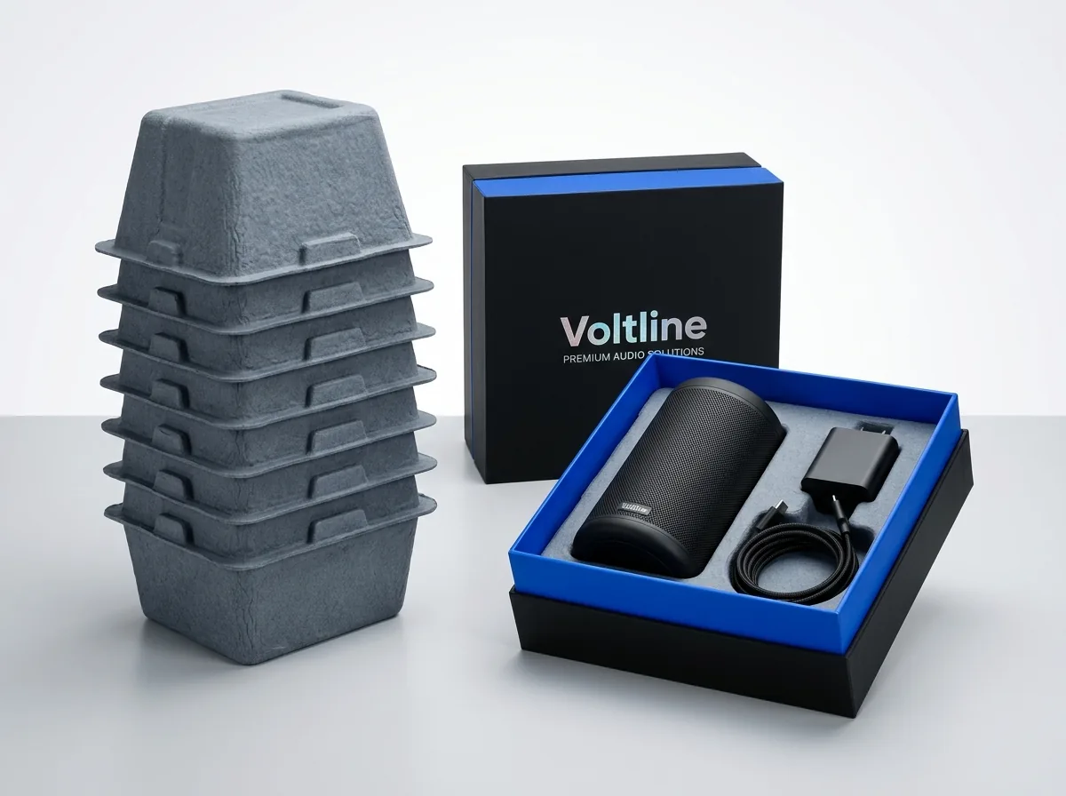
- Draft angle directly sets warehouse pallet nesting density: A 5-degree sidewall taper paired with calibrated stacking lugs lets 60 to 100 empty trays nest into a single waist-high stack, slashing storage space compared with pre-glued foam blocks.
How do wall thickness, corner radii and rib bridges differ between wet-press and dry-press trays?
Balancing sleek retail presentation against parcel drop survival comes down to matching wall caliper, fillet radius, and inter-cavity bridge width to your molding grade. Because hot-pressed wet-press trays compress damp pulp between matched heated metal dies at high pressure, their walls finish thinner, denser, and smoother than oven-dried dry-press cradles, which retain a loftier porous fiber network to absorb heavy impact energy. That difference in wall density changes every tolerance on your 2D drawing, from minimum internal corner radii to the flat top bridge needed between neighboring bottles. You can compare smooth Type 3 against cushioned Type 2 textures in our wet-press vs dry-press molded pulp guide, or check outer carton clearances with our box size calculator. Use this six-point CAD reference table when preparing your product layout
| CAD structural feature | Wet-press smooth (IMFA Type 3) | Dry-press cushioned (IMFA Type 2) | Why the tolerance matters |
|---|---|---|---|
| Sidewall draft angle | 3° to 5° outward taper | 5° to 7° outward taper | Prevents wet fiber tearing on screen release and sets stack pitch |
| Nominal wall thickness | 1.0 to 2.0 mm dense press | 2.0 to 4.5 mm porous wall | Controls rigidity, edge crispness, and shock compression travel |
| Minimum corner radius | 2.5 to 4.0 mm internal fillet | 4.0 to 6.0 mm internal fillet | Keeps slurry flowing into deep corners without thin weak spots |
| Inter-cavity bridge width | 0.35 to 0.50 in (9–13 mm) | 0.50 to 0.75 in (13–19 mm) | Gives two adjacent pockets space for dual sloped walls plus top rib |
| Outer perimeter flange | 0.30 to 0.45 in flat rim | 0.40 to 0.60 in rolled rim | Prevents tray edges from curling and braces outer carton walls |
| Outer box slip clearance | -1/16 in under rigid box | -1/16 to -1/8 in under mailer | Lets packers drop inserts in fast without bowing paperboard walls |

How do perimeter crush ribs and bottom air gaps protect heavy glass jars and electronics?
A molded fiber wall does not cushion a 2 lb candle tumbler or smart speaker by spongy thickness alone; it absorbs impact through geometric suspension and controlled rib deflection. Unlike block custom EPE foam inserts or custom EVA foam inserts that compress through closed polymer cells, molded pulp acts like an engineered shell
- Suspend pocket floors 0.35 to 0.50 inches above the outer carton base: Only the outer skirt and support feet should touch the bottom of your custom mailer boxes with inserts, leaving an air buffer beneath fragile glass bases so flat drops flex the tray rather than shattering glass.
- Bridge cavity walls to the outer skirt with hollow tapered crush ribs: Angled V-shaped or U-shaped gussets spaced every 1.5 to 2.5 inches around a pocket act as sacrificial crumple zones during corner and edge parcel drops.
- Support glass bottles at the shoulder and punted heel, never mid-label: Contacting curved glass at its two strongest structural rings prevents scuffing on paper or foil bottle labels while stopping axial slide.
- Step cavity depths to keep multi-SKU faces flush: When pairing a tall 30 ml serum dropper beside a Squat 50 ml moisturizer jar inside custom rigid boxes, we mold each pocket floor to a different elevation so both caps greet the customer on one flat visual plane.
Know your size? Compare pricing across up to 3 quantities.
Request a Quote →How should you size finger lift scoops, stacking lugs and outer box clearance?
Small ergonomic details separate a frustrating unboxing from an effortless retail presentation and high-speed fulfillment line. Before approving your 2D CAD drawing, verify three functional clearances
- Mold 0.65 to 0.85 inch semicircular thumb scoops on opposite sides of every snug pocket: Hot-pressed fiber walls hold tight tolerances and will not bend aside when a customer reaches in, so contoured finger wells let thumb and index finger grip bottle sides cleanly.
- Include internal anti-jam stacking lugs along the skirt: Without tiny stepped ledges inside the tapered rim, pallet weight pushes nested empty trays together like wedged coffee cups, slowing warehouse kitting crews.
- Size the tray flange after choosing your outer box board grade: Rigid chipboard set-up boxes hold tight square interiors (-1/16 inch tray clearance), whereas folded corrugated mailers roll double side walls inward (-1/16 to -1/8 inch clearance from inside wall to inside wall).
How does CubitPack turn your bottle or device dimensions into a 3D molded pulp proof?
You do not need in-house industrial CAD software to spec custom molded fiber. Whether you are building luxury cosmetic trays for custom skincare boxes, protective cradles for custom electronics boxes, or comparing tooling economics in our molded pulp tooling and foam switch guide, our design team handles the 3D structural geometry from start to finish so your outer box and inner pulp tray fit together on the very first run
- Send physical samples, caliper measurements, or 3D STEP files: Share your exact container diameters, heights, and weights, and our design team builds the cavity draft angles, corner fillets, perimeter crush ribs, thumb scoops, and paired outer box dieline at no cost.
- Transparent custom 3D mold tooling vs zero-die alternatives: Custom CNC aluminum pulp forming screens and press dies are quoted transparently per project alongside 250, 500, 1,000, and 2,500+ unit price breaks so you can see how mold setup amortizes across larger runs. If a short pilot order needs zero tooling charges first, we can quote custom cardboard inserts or custom honeycomb inserts side by side.
- 3D digital mockup before payment and 10 to 14 business day production: Review your 2D CAD drawing and interactive 3D mockup before paying, request our $50 general sample kit (credited to your first order) or a custom physical pulp prototype (priced per product), and receive free delivery across all 50 US states.
What are the five most common molded pulp CAD design mistakes?
Check your tray brief against these five geometry pitfalls before machining 3D aluminum tooling
- Specifying 0-degree vertical pocket walls like die-cut foam, causing wet pulp fibers to scrape and tear off the forming screen.
- Drawing sharp 90-degree bottom corners instead of 3 mm or wider fillets, creating paper-thin corner spots that split on parcel drops.
- Letting heavy glass pocket floors rest directly on the outer carton bottom instead of suspending them above a 0.35 to 0.50 inch air gap.
- Leaving less than 0.35 to 0.50 inches of bridge width between adjacent wells, leaving no room for dual drafted sidewalls to meet.
- Forgetting 0.75-inch semicircular finger lift scoops around snug rigid jars and devices, forcing customers to turn the box upside down.
Packaging for this



Ready to order molded pulp inserts? Compare up to 3 quantities with a free 3D mockup.
Request a Quote →Questions about molded pulp inserts
Can custom molded pulp inserts have 0-degree vertical cavity walls?
Standard wet-press and dry-press pulp trays cannot use 0-degree vertical walls because damp fibers lock onto the metal screen mold during vacuum forming. Designing a 3 to 5 degree taper on smooth wet-press trays or 5 to 7 degrees on dry-press cradles ensures clean release and smooth walls.
How thick are the walls on a custom molded pulp box insert?
Hot-pressed wet-press trays (IMFA Type 3) typically compress to a dense, card-smooth 1.0 to 2.0 mm wall caliper, whereas oven-dried dry-press cradles (IMFA Type 2) form thicker 2.0 to 4.5 mm porous walls engineered for heavy drop absorption.
How much space is needed between two cavities in a molded fiber tray?
Plan at least 0.35 to 0.50 inches (9 to 13 mm) between adjacent pockets on wet-press trays and 0.50 to 0.75 inches (13 to 19 mm) on deeper dry-press cradles. Because both neighboring walls slope outward, deeper pockets require wider top bridges so walls do not intersect.
Do custom molded pulp inserts require custom mold tooling fees?
Yes. Unlike flat paperboard inserts cut with zero-fee steel-rule dies, 3D molded pulp requires CNC-machined aluminum forming screens and press dies quoted transparently per project. Standalone orders start at 250 units, and higher quantities amortize the mold across your run.
Should I finalize my outer rigid or mailer box dimensions before designing the pulp insert?
Wait until both are engineered together. Adding a 3 to 7 degree draft angle, 0.40-inch perimeter flange, and crush ribs around your bottles determines the exact interior footprint needed. Our design team builds your pulp tray CAD and outer box dieline together for free.
Can you mold subtle retention bumps to hold products in place without undercuts?
Yes. While deep horizontal undercuts cannot release from a solid one-piece vertical press tool, small calibrated friction nibs molded along drafted wet-press walls can gently grip bottle shoulders or charger casings during transit without tearing fiber during demolding.
Still have a question? Ask a packaging specialist.
Request a Quote →Request your molded pulp inserts quote
Tell us your size and quantities, and one dedicated account manager prepares pricing for each tier.
- Free design & AI-to-print studio + 3D mockup
- No die or plate charges · 4–5 day rush available
- Free shipping to all 50 states
- 10% off your first order
We verified wet-press (IMFA Type 3) and dry-press (IMFA Type 2) draft angles, corner fillet minimums, wall caliper bands, and crush-rib suspension principles against International Molded Fiber Association (IMFA) technical standards, TAPPI pulp forming literature, and ISTA parcel drop test procedures. A packaging specialist checked every dimension row and CubitPack offer. Spot something wrong? Tell us and we fix it.
Sources
- Type 2 transfer dry-press and Type 3 thermoformed wet-press draft angles, wall thickness ranges, and surface finish tolerances.
- Bottom air-gap suspension clearance and perimeter crush-rib energy absorption for fragile glass and electronic devices.
- Slurry fiber drainage across internal corner radii and dimensional behavior of molded paper pulp.
What changed
- November 16, 2026: First published with 6-row wet-press vs dry-press CAD geometry matrix, crush-rib suspension cross-section, and thumb-scoop clearance rules.
More guides
New packaging guides by email
Sizes, materials and design tips. Unsubscribe anytime.